
Android/Arduino RF Outlets Selector
Overview
Here’s a great little project I implemented with Arduino and Android – switching outlets from my smart phone!
I started with off the shelf RF Wireless Outlets. At $6 per outlet, they are a complete steal. I got lucky and found all 4 channels of these wireless/RF outlets at a local Big Lots. I’ve seen them at Home Depot too. And of course they’re available on Amazon. Compare that pricing to one unit of the Belkin WeMo Switch
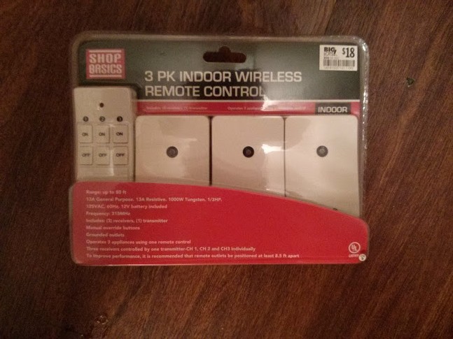
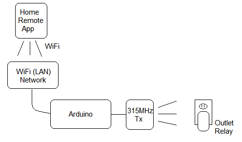
Diagram:
Parts List:
-
315MHz Wireless Outlets –
Woods 13569 Indoor Wireless Outlet (3-Pack) on Amazon - 315MHz Chip –
SMAKN 315Mhz Rf Transmitter and Receiver Kit on Amazon - Arduino –
Arduino UNO R3 on Amazon - Arduino Ethernet Shield –
Arduino Ethernet Shield R3 on Amazon
All the code is on Bitbucket. There is also a simple remote control Android / IPhone application available in the Google Play and ITunes stores. (Better looking than in the video, too!)
In the last year or so, there may be better options than Arduino for the brain, but that code rewrite will have to wait until another day. This is what the circuit looks like… very simple, just hook up the 4 pins of the transmitter to the correct place and you will be ready to load the code onto the Arduino!
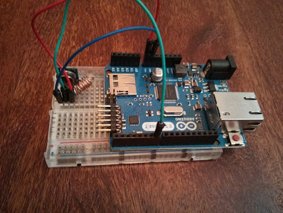
The Arduino can hook up to your router via the Ethernet shield, and when it’s turned on will be running a web server at the URL: {IP address}/outlet?outlet={outlet}&channel={channel}&state={state}
And of course the Android and IPhone app comes with a UI added to those URLs, so you can click a toggle button for all the outlets, rename them, etc. See more about the App here.
I based the code on a cool outlet project that was pretty mature, called RC Switch, but in Europe the RF protocols and outlets are a bit different. There was also a reference from Instructables, but those RF on/off timings didn’t match my outlets. If you don’t have luck with my code as-is, modify the pulse length timings to match what is found here. There may be more variants that look the same, as a lot of these outlet modules look the same but are rebranded.
Reverse Engineering / Troubleshooting
Hopefully during the project you can implement it in a straight-forward way, but if the same protocol does not control the relays, read on to how I troubleshot this project originally…
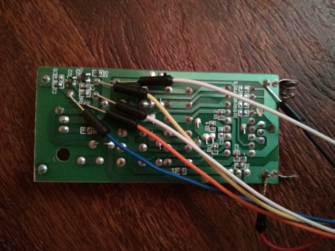
To figure out the problem above, I used the Arduino as a logic analyzer to figure out what exactly wasn’t working, and that was probably the most fun part of the project. I soldered leads onto the stock wireless remote to spy on the signal that was being transmitted, and saw the digital signal graph on my TV screen. Amazing! As a programmer, I forget sometimes that there is electricity flowing through everything and changing direction every few nanoseconds.
This Arduino logic analyzer is a great open-source code project, and saved me big time here. It has 500 kHz max resolution, but since there is only 1kb of RAM, you’re limited to 1024 samples. That resolution was actually so good, that the first few times I thought it wasn’t working… I was zoomed in too far and didn’t see any transitions. As soon as I zoomed out to 1 kHz, I saw everything! And 20 kHz was finally the sweet spot to measure the timings accurately.
This is how I instrumented the remote control for use with the logic analyzer. I soldered many jumpers onto the circuit — only 2 carried the signal I wanted. The orange wire, and the right-most white wire both had the correct waveform — though the white one was inverted. I also provided power from the Arduino, since the remote had a 12V battery, some traces might have been carrying too much juice for the Arduino!
Feel free to provide critique or suggestions!
Ze Germans? Really?
Is it possible to change the colour of the blinking LED with this interface? I would like to have the LED start white and then flash orange when connecting and then burn steady pink when connected and flash blue if the Arduino detects a change in the incoming voltage.
[…] interface with it? A quick search on a hackaday lead me to others who have done similar, such as this and this. It was possible and not too […]
[…] Visit his website to learn more and for all the code. Andriod Arduino Ethernet W5100 2014-01-28 admin Share ! […]
Ok.. love your work first of all, second I have been using these remotes for several years and can help you with some more info and facts. first off they actually go from A – F for a total of 18 devices to control however, that’s not the case when you dig a bit further.. with a little modification you can actually control many more devices to the tune of 128 devices by my count, If your interested let me know I can send you photos of what I have learned and how tos.. and more info on these sweet remotes..
Mark
I would be really interested in knowing how you are able to expand this project out to control 128 outlets. I would like to hack these to wire them in as 3 way light switches across the house instead of just power outlets. Looks like it should be possible.
Hi Mark,
Your post on 33snowflakes is almost a year old but I really liked your offer to share
what you’ve learned about the Shop Basics/Woods 13569 Indoor Wireless Outlet remotes
(http://www.33snowflakes.com/blog/arduino-wireless-outlet).
I’ve just purchased a 3-pack and am starting my Home Automation project.
Thanks!
Ridge
I’ve talked to Mark via email previously. Apparently, it’s possible to buy zones E and F off-the-shelf from some places. And to go up to zone P, you just open up the receiver device, here are Mark’s instructions: “once you change your software, you simply take any receiver indoor or out , open it up coming off the ic chip on the board is 4 etch lines simply scratch off the ones you don’t need to match your binary letters,,,,, 0100 scratch second one… 0101 scratch 2nd and forth”
I haven’t tried that, but anything you do to increase # of zones beyond 4 (so beyond 12 devices) will require updating [RCSwitch.cpp](https://bitbucket.org/thebostik/arduino-projects/src/b271b399cf67f7ce259dc3a705ea4fdd65b51fd9/OutletWebControl/RCSwitch.cpp?at=default) and add more logic blocks like in line 241. Also the phone apps just support the 4 zones by default and would need minor changes as well. If you’re serious about making the change, get in touch with me and we’l chat in more detail.
Good luck with the project.
I just wanted to thank you for mentioning those 4 traces grounded from the IC. I already had a 3-pack of these wireless outlets, but picked up a second set today when I spotted it on a clearance shelf at Home Depot… and hoped they were on a different channel. It turned out both sets were set to the same channel, unfortunately.
Without your comment, I wouldn’t have known I could simply cut a trace on each board to solve my problem.
I’ve yet to find any documentation on the AUT980202-B – At some point I might consider wiring one of my remotes up to a networked Arduino, but I’d like to know more about this chip if anyone has information.
Thanks for the great write up. The switches I got from walmart at xmas the physical design has changed slightly. They are still based on the aut980202-B encoder chip. The ones I got where channel ‘F’, and the channel code is ‘0000’.
I now have sets A,E,F working. Channel “E” I’ve had form some time and the channel code is ‘1100’. Code was easy to tweek to add the additional channels.
Does anybody know how to create channel G by scratching the traces? I might have to replace a remote that somebody lost and can’t access or test the receiver they are using.
Hello! Awesome project! I’m after a less ambitious goal… Or perhaps, depending on how you look at it, maybe a more difficult one… What I would like to do is possibly reprogram the main chip on one of these or find some other method so that its initial state is to turn the relay on when it first boots up or gets power from the socket… this is so that I can plug into the light switch controlled socket in my room when I first walk in and have the lights go on… and then later on at night use the remote to turn it off… Unfortunately as it stands, when it first received power it starts listening for the radio commands I presume, but its initial state is not to turn on. Any help in this endeavor would be greatly appreciated! Thank you!
Hi, thanks for commenting. For relays, this is handled with normally open / normally closed. I’m not sure how the wireless relays this post is about handles this. For lights, prices of commercial switches has come down a lot, this post is pretty long in the tooth these days. Good luck with your project!